Table of contents
As described on the main technology page, the sensors used for this system measures various characteristics of the compost heap and is constructed of both e-waste as well as off-the-shelf components.
This page mainly covers the hardware aspects of the sensors. For some details on the code needed for them, refer to the Source code page.
Functionality
The sensor system is intended to gather data on the current state of the compost heap and make that data available on the Internet of Things, while being installed where electrical and Internet access may not be available.
The data comes from multiple sensors that are connected to the system and are inserted in and around the compost heap. A combined methane and temperature probe monitors the volume of methane emitted by the heap as well as its current temperature, to ensure that the composting process is not becoming anaerobic (i.e. too much methane). External temperature and humidity sensors allow comparison to the environment on the outside of the heap.
For operation out in the field, the sensor system is equipped with a wireless transmitter and receiver that uses mobile data to transmit the data, meaning it is not dependent on local wireless access. It is also equipped with a rechargeable battery pack and solar panels so it can run indefinitely without another power source.
The system uploads the data collected by the different sensors to a cloud data service. The one in the Substation33 design uses ThingsBoard, but a different one can be selected. This data can then be shown in a visual dashboard on that service, or downloaded or viewed by other means (such as this project’s mobile app). When creating your own sensor system, you should look up how to connect to and upload data to the service you choose.
Components
The sensor system is made up of several different components, several of which are recycled from e-waste in Substation33’s design. The basic design is a solar-powered microcontroller with several sensors connected to it, which will be covered in later sections.
Main system
For this project, the microcontroller used for the sensor system is an Arduino, though others such as a Raspberry Pi can be substituted in if those platforms are more suitable for your purposes. This will also affect some of the other components that are needed, though it is out of the scope of this page to describe all possible alternatives.
Because of the location of the sensors, this particular design made use of solar panels and a rechargeable battery pack. The latter is one of the components that was created via salvaging e-waste. Old laptops and their batteries are a common item to be disposed of as e-waste, and often it is only one or two cells in a battery that do not work. Therefore, the rest of the working cells can be used for powering devices, and that is the case for this sensor system.
As the sensor system needs to transmit data to the cloud, it needs a way to communicate via the Internet. So that it is not reliant on having an accessible wireless network, this design uses a 3G wireless adapter and a SIM card with a data plan.
The video below gives an overview of the steps to assemble the core components of the sensor system.
Please note that the “sensor platform board” mentioned in the video and parts list is a Substation33 design and so you will need to either create a similar component yourself, or substitute in off-the-shelf components.
For example, in the video, the solar panel and battery are connected to the sensor platform board. There are instructions online – such as on Arduino’s project hub – for how to connect an Arduino to a solar panel and a single battery, which could be the basis for developing your own solution.
|
|
Alternatively, we have also provided a list of materials below as well as the steps to construct it. These steps include details that aren’t covered in the video. Note that you can substitute in similar parts; the links are examples.
Please note that these steps assume you have knowledge in how to properly work with electrical equipment – if you don’t, you should find someone who can assist you, as working with powerful lithium cells can be dangerous.
Materials required
- 8× 18650 lithium-ion battery cells
- 2× 2W solar panels
- 4× copper wires
- Sensor platform board (custom designed)
- Arduino Mega
- 3G wi-fi shield for Arduino
- 3G data enabled mobile SIM
- PVC pipe (must be cut to size. Any other suitable container can be substituted in)
- PVC pipe lid (if using the above)
- 3D printed solar panel holder (source STL file)
- 3D printed battery and sensor platform board holder (source STL file)
Tools required
- Hot glue gun
- Wire strippers
- Soldering iron
- Solder
- Screwdriver
- 3D printer
Steps
- Glue the 3D printed solar panel holder to the top of the PVC pipe lid.
- Drill holes into the PVC pipe lid through those of the solar panel holder, ensuring they are large enough for the copper wires to fit through.
- Connect four wires to one of the terminal block connectors – two in each side – and thread each pair through one side’s holes in the lid/solar panel holder.
- Solder the pairs of wires to one solar panel each, and then glue the solar panels to the top of the solar panel holder.
- Connect batteries into parallel pairs using nickle strips, before wiring those pairs up in series to the other terminal block connector.
- Slot both the sensor platform board and battery pack into the 3D printed holder and screw the former in.
- Attach both the Arduino Mega and the 3G shield into the sensor platform board. Make sure the SIM is inserted into the latter.
- Connect the battery pack and solar panels to the sensor platform board, and ensure the Arduino receives power.
- Insert the system into the PVC pipe and screw on the lid.
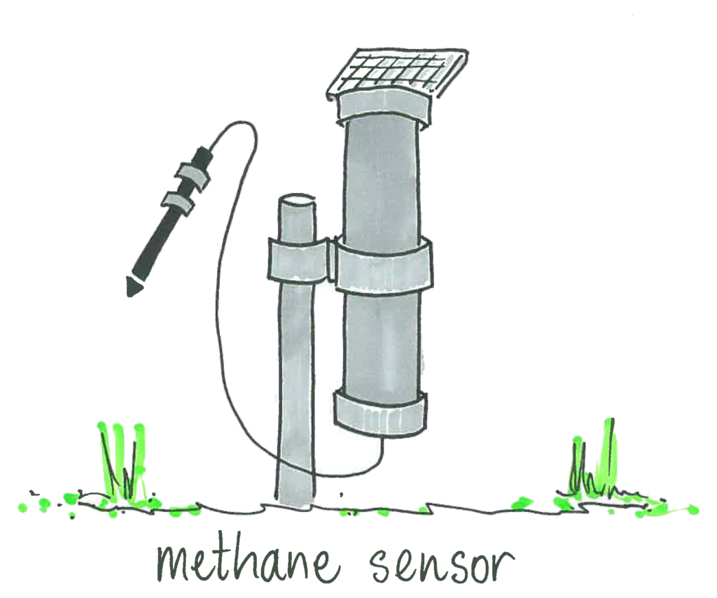
Methane and temperature probe
One of the important considerations for a compost heap is the volume of methane that is being produced. If there is not enough air in the heap, it can start to become anaerobic, and give off an increased level of methane.
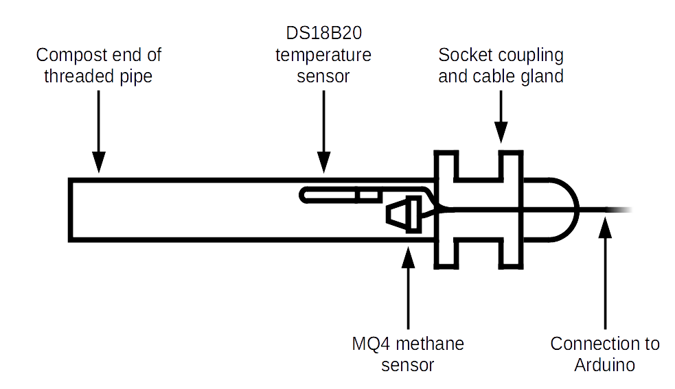
To measure this, the system includes a specially constructed probe that can be inserted into the heap. This includes a MQ-4 methane sensor as well as a DS18B20 temperature sensor. In order to measure the internal state of the compost heap, these sensors are placed inside a narrow, long pipe. The probe can then be inserted inside the compost material without the sensors themselves touching the material, preventing them from being damaged by moisture or the organisms in the heap.
The diagram below shows the construction of the methane and temperature probe:
The video below gives an overview of the steps to construct the probe:
|
|
Alternatively, we have also provided a list of materials below as well as the steps to construct it.
Materials required
- 3/4 inch irrigation fittings
- 300mm threaded pipe
- 3/4 inch socket to socket coupling/threaded pipe socket
- 30mm threaded joiner/end cap riser
- 25mm cable gland
- MQ-4 methane sensor
- DS18B20 temperature sensor
- USB cables
- Three pin terminal block connectors
Tools required
- Hot glue gun
- Wire strippers
- Soldering iron
- Solder
- Screwdriver
Steps
- Cut the ends of the USB cable off to expose the wires inside. These wires should also be stripped by at least 5mm to expose the copper inside the sheath.
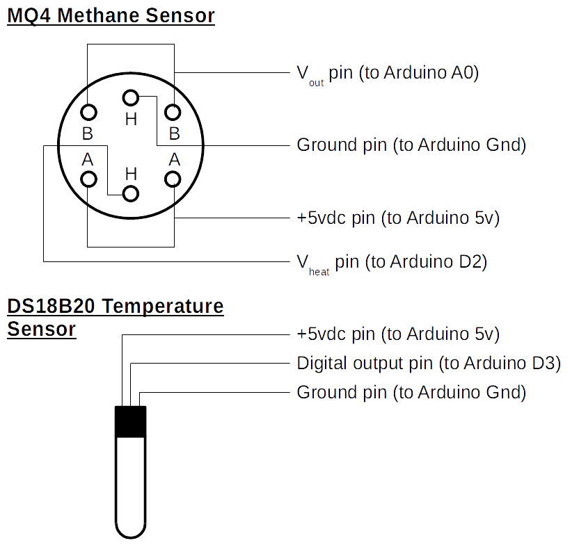
- The wires should then be soldered to the two sensors. Both sensors can be soldered to the same cable as shown in the video. The diagram below shows the required connections:
- If required, the threaded pipe should be cut to allow it to hold the sensor. This should be the end with the thread (the other end is what goes into the compost heap).
- The sensors should then be inserted securely into the threaded pipe.
- The socket coupling should then be attached with the sensor wires threaded through it, as well as the cable gland.
- To finish off the probe, the wires on the other end of the USB cable should be inserted into two terminal block connectors.
Moisture sensor
While not used in Substation33’s design, one of the possible sensors that you may want to use in your own system is a moisture sensor, used to determine how much moisture is in the soil.
There are several different models available, but for Arduinos and other microcomputers, they are typically of a two stake design that can be inserted into the soil like in the diagram below.
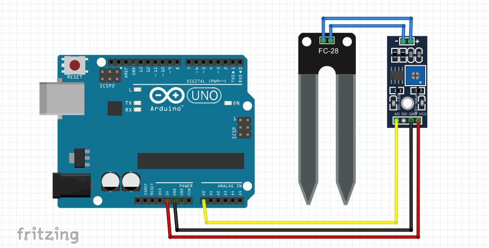
The moisture sensor used in this example can be attached to the microcomputer without any need for soldering; however, it may need a longer connection if the sensor will be far away from the microcomputer. The video below shows how to extend the cable of the sensor:
|
|
Alternatively, we have also provided a list of materials below as well as the required steps.
Materials required
- Moisture sensor
- USB cable
- Heatshrink
Tools required
- Wire strippers
- Soldering iron
- Solder
- Blowtorch
Steps
- Cut the ends of the USB cable off to expose the wires inside. These wires should also be stripped by at least 5mm to expose the copper inside the sheath.
- Cut a piece of the heatshrink and insert it over the sensor end of the cut cable.
- Solder the wires from the USB cable onto the sensor.
- Slip the heatshrink over the connection to the sensor and use the blowtorch to melt it into place.
- Solder the other end of the wires to the interface board.
- Connect the interface board to the Arduino or other microcontroller using the regular supplied cables.
Water level sensor
Another possible sensor that can be used on the system is a water level sensor. There are sensors available that uses a resistive strip referred to as “eTape”. This can then be inserted into a container that fills up with a liquid which affects the resistance of the strip and which the level of the liquid can be determined.
The eTape water level sensor may come with its own tube and cable gland, but in the case it does not come with one, you will need to assemble it inside one itself before connecting to the microcomputer. Once connected it can be read as if it is an analog voltage based sensor. This is shown in the below video:
|
|
Alternatively, we have also provided a list of materials below as well as the required steps.
Materials required
- Water level eTape sensor
- USB cable
- PVC pipe
- Irrigation plug
- Threaded joiner/end cap riser
- Socket to socket coupling/threaded pipe socket
Tools required
- Hot glue gun
- Wire strippers
- Soldering iron
- Solder
- Blowtorch
Steps
- Cut the ends of the USB cable off to expose the wires inside. These wires should also be stripped by at least 5mm to expose the copper inside the sheath.
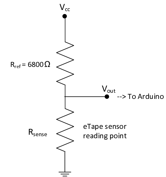
- Pre-solder one end of the USB cable’s wires, before soldering them to the jumper for the eTape sensor. They should be wired according to the below schematic. The jumper is used to avoid damaging the delicate eTape sensor.
- Heat up the hot glue with a blowtorch and then apply it to the connection in order to seal it from the environment. If you have other materials such as a heatshrink or silicon, they can also be used.
- Create a cap for the PVC pipe by assembling the irrigation plug, end cap riser and threaded pipe socket. The end cap riser should have slots for the eTape sensor to fit into, and the wire should be able to pass through it.
- Insert the wire through the cap and plug it into the eTape sensor, and insert the eTape into the cap.
- Place the eTape connected to the cap into the PVC pipe.
- Connect the other end of the USB cable’s wires to the microcomputer as per the schematic.